Electronic control unit (ECU)of cars
Electronic control unit (ECU)of cars
Author: Leonard
Role: manufacturing supervisor
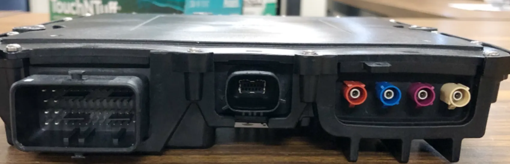
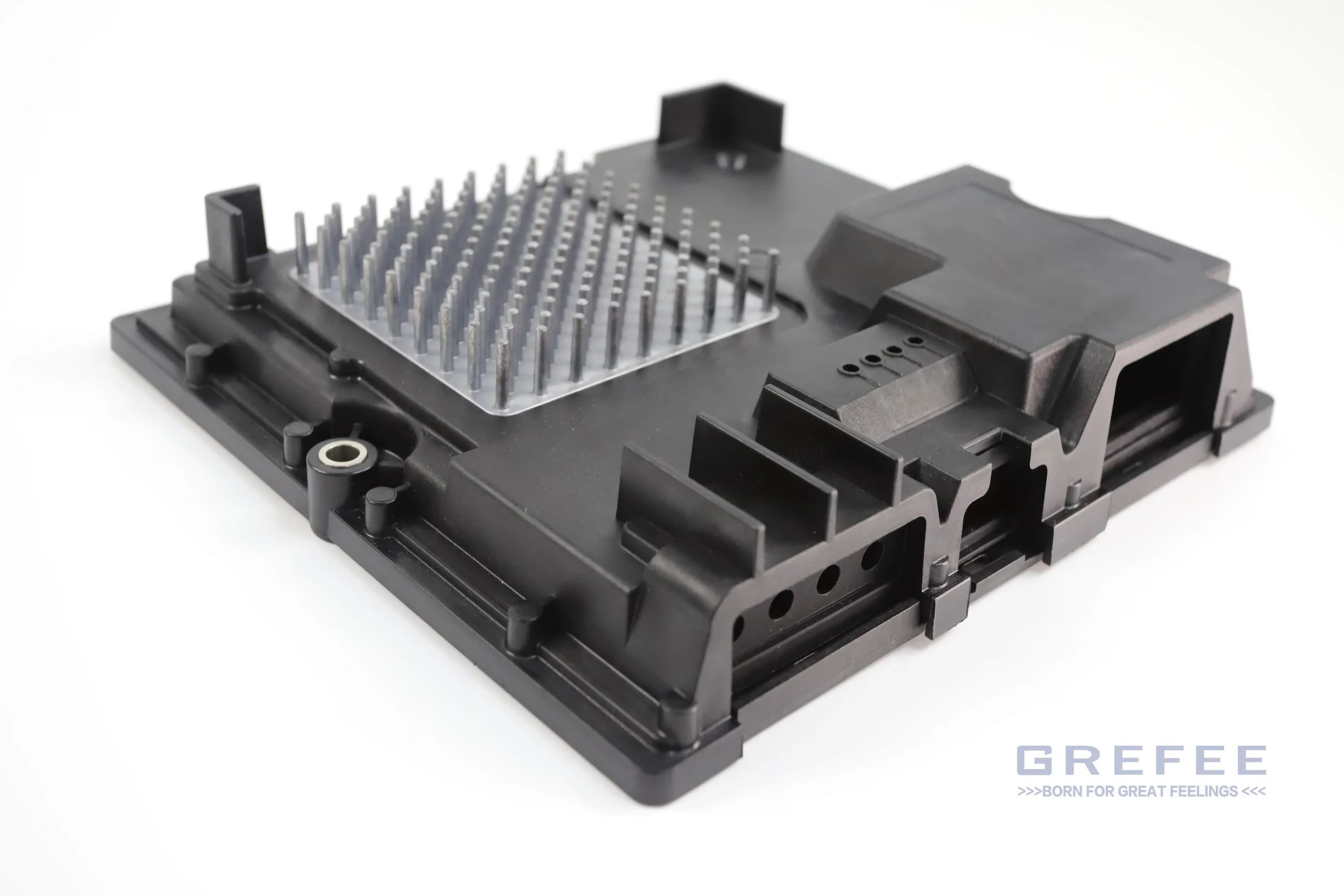
Today, we will introduce the ECU of cars that is applied into multiple fields. The ECU is mainly utilized at the lights, windows, radars and other controlling units. The ECU has many features, such as dust proof, isolation, and heat radiation, etc.
product introduction:
Material: the inside parts of cars need to use material that is hard and tough enough as well as fireproof. It is quite strict on size to prevent the electrical parts inside products from damaging under special circumstances. Generally, we use nylon with fiber due to the better mechanical performance and high temperature and corrosion resistance.
Surface requirement: as the inside parts do not need high surface requirement, and most of them are SP1-B2 standards. Only a few of products requires texture or other processes on the surface.
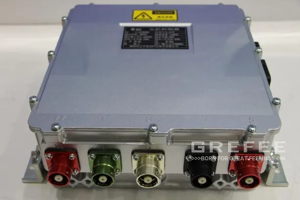
Size: strict size requirement. Product deformation ±0.1MM, and the sealing requirement can be as same as the standards for IP68.
Function: Internal electronics in the original device generally need to be powered on, so the product generally has functions of heat dissipation and fire prevention.
This series includes injection molding, die casting, lathing ,compression molding , of which three sets of plastic molds, one set of die-casting mold, one set of rubber molds, and one lathing process accessory.
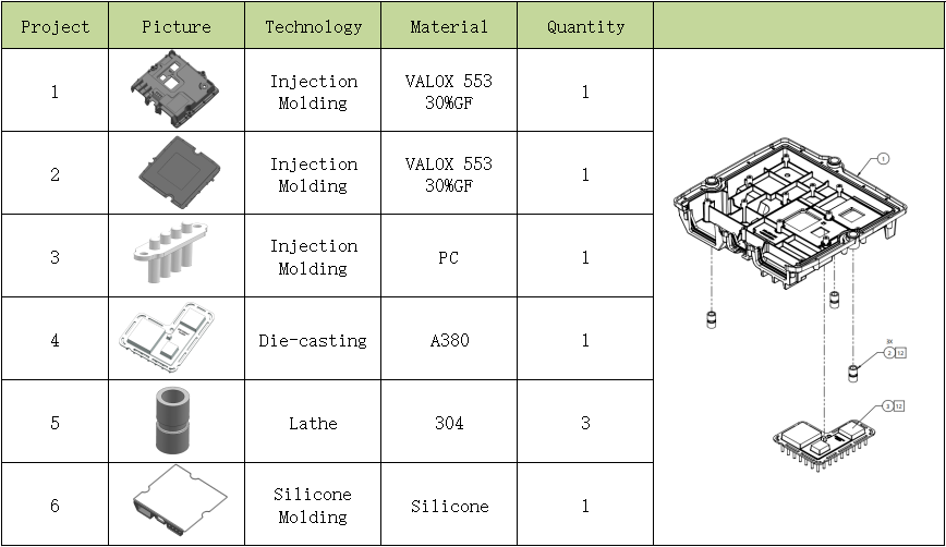
Processes application: stamping processing, lathe processing, injection molding, compression molding, die-casting molding.
Post processing applied: polishing, texture, passivation
Materials used: VALOX 553 30% GF PC、LSR、304、A380
The difference between injection molding and compression molding:
The materials for injection molding are mostly plastic hard materials, such as PP, ABS, PC, PMMA. Injection molding is mainly used in industries such as casings, automotive parts, toys, daily necessities, etc. The material used for compression molding is soft material, such as NBR and LSR, mainly used for internal components of various equipment, such as gaskets, sealing rings, shoe soles, etc. The principles and processes of injection molding and compression molding are also different:
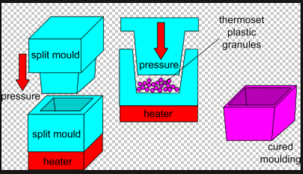
Injection molding: The material is heated and injected into the mold under the injection molding machine pressure, and then cooled (with a relatively fast cycle)
Compression molding: First measure the material and place it in the mold, then apply pressure and heat (relatively slow cycle).
Embedded molding means to put the embedded parts of different materials into a mold according to the drawing, then inject material into the mold with the pressure to integrate with the insert parts or completely wrap the insert parts until the plastic material cools down and solidifies the embedded parts in the desired position.
Internal embedding: as we mentioned earlier, nuts that need to be placed inside the mold before injection molding.
Hot melt embedding, either can be done by machine or manually, which works by using a heating mechanism to heat up the embedded part and press it into the injection molded part after it is completed. Compared with embedding inside the mold, the equipment for hot melt is relatively simple, the investment cost is low, and the consistency is strong. However, the stability of hot melt is relatively low, and there is a risk of detachment.
Press in type, mainly cold pressing, refers to directly pressing plastic parts without heating. It is mainly used in thermosetting plastics that are not suitable for hot melting or difficult to melt. Although the performance of the press in process is inferior to that of in mold embedding and hot melting, it is the most economical choice because this process can be easily installed without equipment. The shape of the nut varies depending on the process
Application of inserts:
The most used frequent internal inserts of plastic products is copper screw, which is mainly to add the connection strength between plastic parts. Cooper screw is an important connector with great conductivity and excellent corrosion resistance. Thus, it is widely used in agriculture and daily lives. The major function of screws is to make sure the connection toughness and can reuse.
When the connection toughness needs to be higher, there must be sufficient torque to tight the screws in case the loose of two plastic parts. As the nuts need to put into the mold manually, which extends the injection molding circle. When a product has many screws that need to be put into the mold, we can select nuts to put fixture, which shortens the production circle.
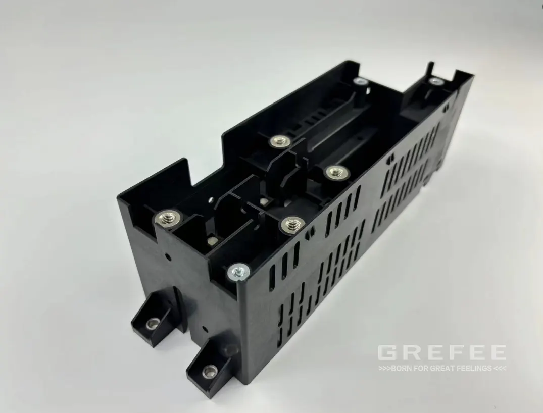
Another function of plastic internal inserts is to increase the strength. When the space is limited, we can consider to add inserts inside to make sure the strength of key areas, which is the most common on automotive parts.
Another type is used at the external shafts or holes. The fastening connection of plastic parts or seals belongs to soft connections, such as in areas prone to wear and overlap with other high-temperature areas. The most common type of component is bearings, which are mostly made of metal.
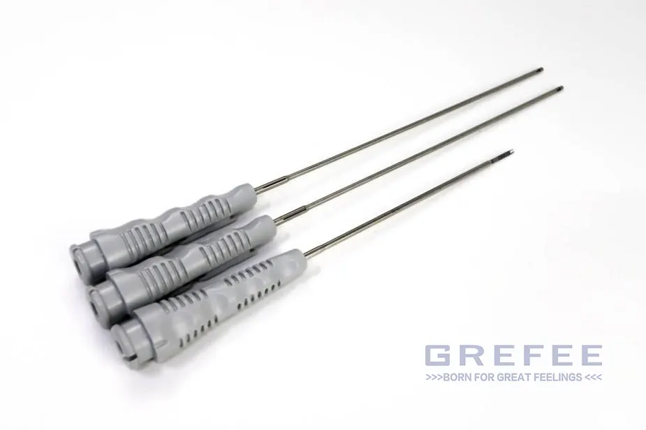
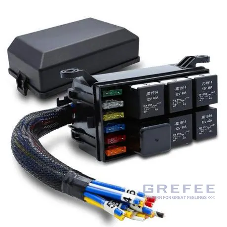
Other medical supplies such as puncture needles, electronic products such as battery packs, spring clips, and wire harness plugs; Industrial products such as the battery box heat sink we customized for our customers.
Plastic product evaluation:
According to the sheets, we can see that the main material used is PA6+30% GF. Due to the high proportion of GF added to the material, its flowability has deteriorated.

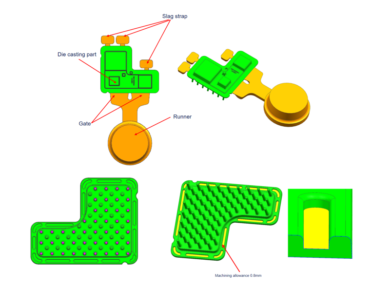
What makes this product hardest point is the extremely high size requirements. The bottom shell material PA6+GF30 and the die cast product material A380 are overmolded. We need to consider the flow pressure loss experienced by the PA6+GF30 plastic material when passing through the A380 die cast material, as well as the temperature effect of the A380 die cast product on the size and pressure of the encapsulation process. Thus, after many times of mold flow analysis simulations, we eventually found out the best injection solution.
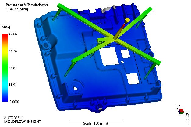
Secondly, in order to reduce the temperature loss of plastic materials close to die-casting part, we also need to heat the A380 die-casting product during the encapsulation injection molding process to ensure that the plastic flow is not affected and maintain normal flow speed. From our injection mold flow simulation scheme, it can be seen that the pressure difference at each product position is minimized, which can fully ensure the overall size of the product
Uniform material thickness is the fundamental to avoid product defects. Through analysis, it can be seen that the material position at the corner of the product is less than 0.5mm, while the bottom of multiple bone positions exceeds the main wall thickness, which may cause shrinkage or dents on the surface of the product. We ensure the rationality of the main material position of the product by reducing the thickness of the bottom of the ribs position, increasing the wall thickness at the thin material position, and adding rounded transitions at the corner to reduce the possibility of surface defects.
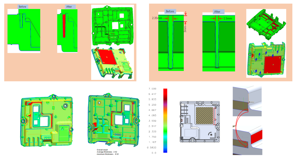
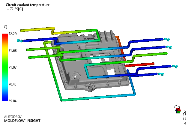
Proper cooling system is the guarantee for the quality of injection molded products. We adjust the cooling system layout according to the position of the injection gate, and each injection gate has a separate cooling transportation control to make sure that the inlet and outlet temperatures of each water lines are controlled within 2 degrees. At the same time, the surface quality of the product is also guaranteed.
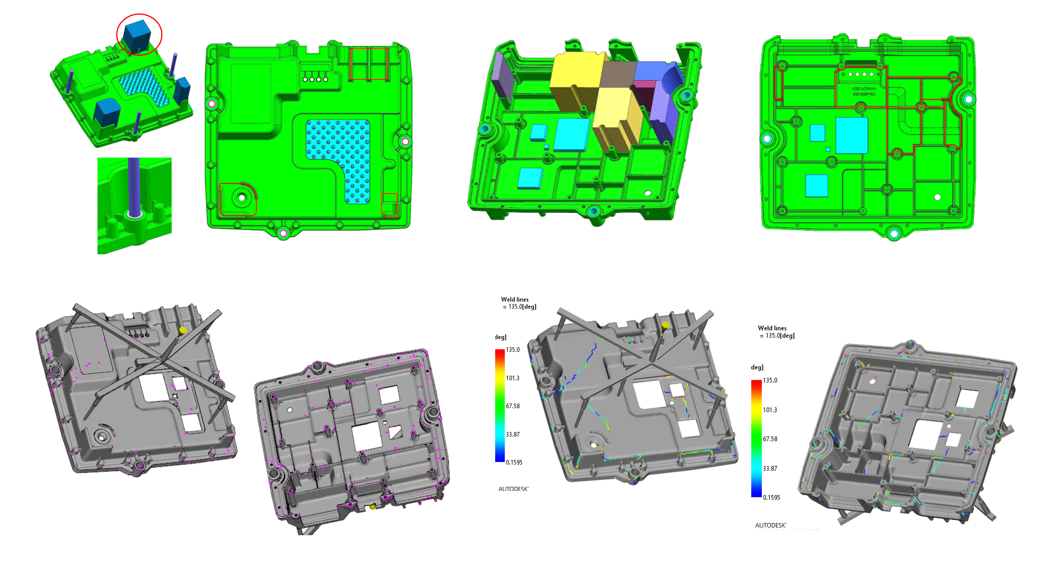
Due to the fact that this series of products are embedded with stainless steel and aluminum parts in plastic parts, there may be issues such as trapped air/venting, edge bonding lines of embedded parts, and short of material during injection molding. To avoid these problems, we have analyzed the mold flow of the product and added venting groove for trapped air. We have also added a large number of air vents at the internal ribs positions of the product to ensure that the air inside the mold can be smoothly out during the production process.
Heat sink:
In the heat sink die casting molds gate feeding solution, we adopted into the straight side gate, and more around the products to create a connected large plane with air vents. In addition, it largely reduced the sand holes inside of the products maximum. In the post-processing, the product was wrapped inside plastic parts, and we have considered that there are no particularly high size requirements in this area during the design process, so we used stamping process that has better time and cost efficiency. At areas with assembly requirements and functioning areas, we choose to reserve steel material during die casting, then using CNC machining to meet the requirements of key dimensions.
Design of insert mold:
The design of insert molds differs from other monochrome mold designs in that the sealing position and fixing method may vary depending on the shape and size of the inserted parts. As the three circular gaskets are covered with plastic, we use a middle sleeves pin positioning and a fixed height of the cavity and core mold planes to seal the adhesive. Therefore, the three gaskets need to be arranged on the core side. The heat sink is positioned at 8 points on the periphery, supported by multiple single points in the middle, and sealed with 3mm adhesive on the surrounding plane. Other positions are designed to avoid gaps for easy installation on the mold during production. As the bottom surface of the heat sink has no obvious features, it needs to be installed on the cavity side during production to prevent it from falling off during the mold closing process.
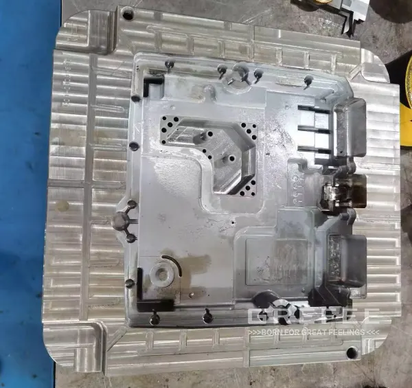
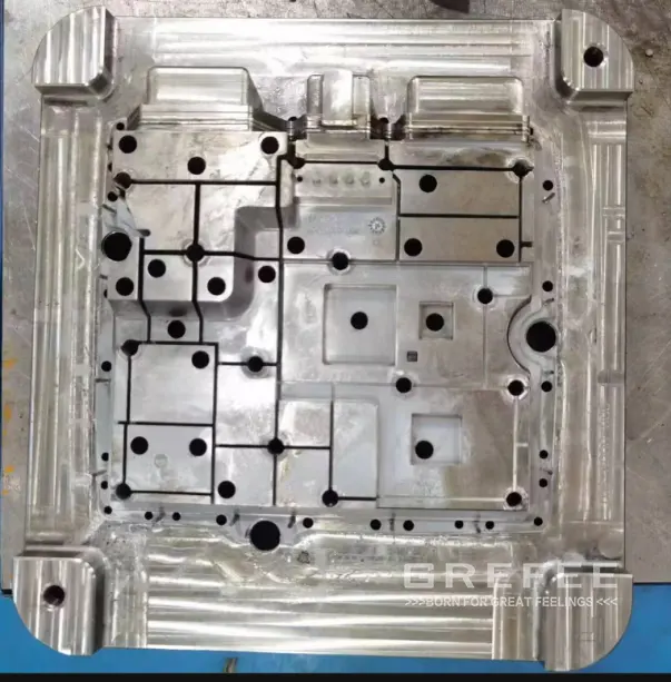
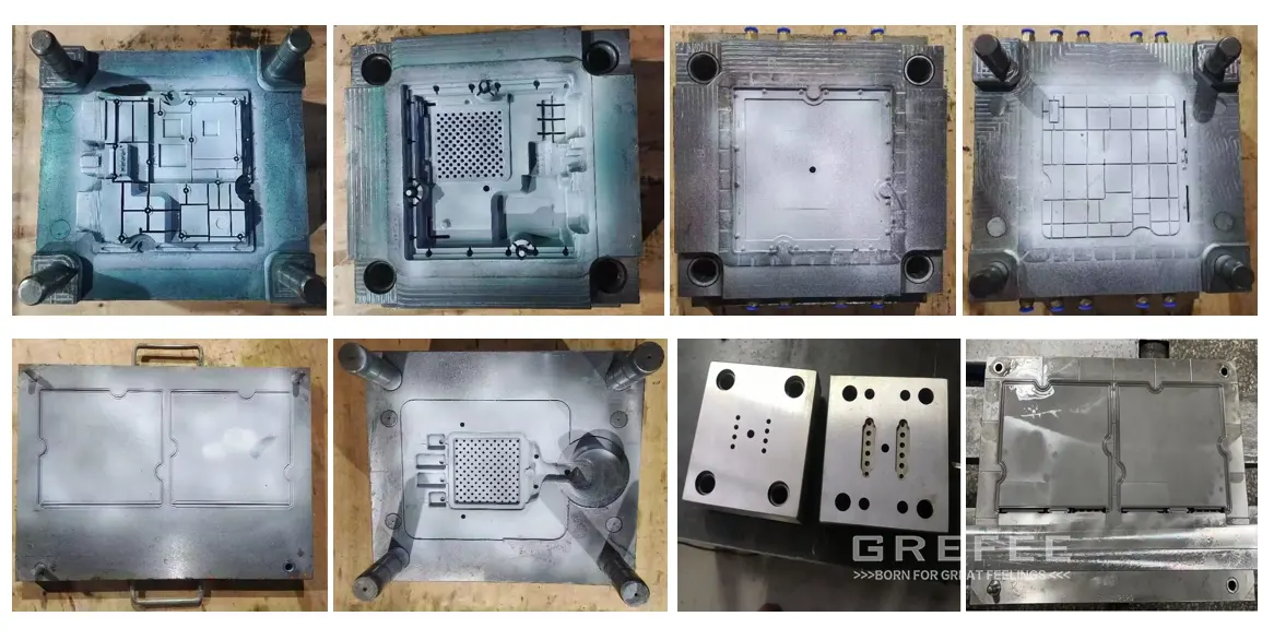
Mold manufacturing and post processing
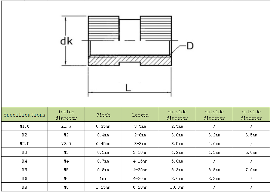
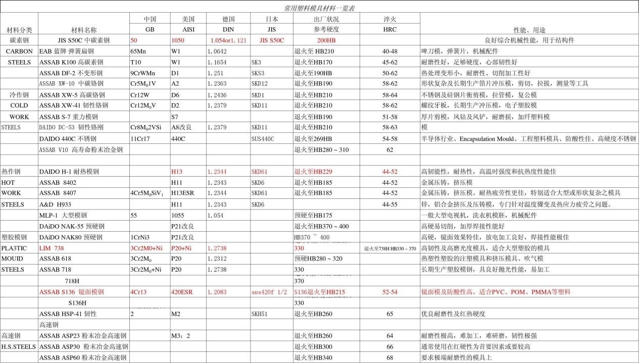
In terms of the material selection, we used S316 hardened material (HRC48-52) of ASSAB due to its good wear resistance, corrosion resistance, and heat resistance. For die casting mold material selection, we used ASSAB 8407 hardened material (HRC48-52). The material selection should be based on the mold life and surface requirement as well as material performance. The below table is the common used specification information of Mold Steel
Production
Before injection molding, we need to bond the heat sink and mold together to make sure the heat sinks can be attached to mold perfectly to avoid injection leaking or burrs and other problems. Before each production, it is necessary to install the inserted parts on the mold for mold clamping testing to check whether there is a risk of the inserted parts falling off. During production, it is necessary to first check whether there are any defects in the various positions of the heat sink, and then use an air gun to blow the heat sink clean, especially whether there are particle problems on the front and back of the heat sink, to prevent the mold from being crushed by particles.
Each project is processed in accordance with APQP, and we have over 100 QCs involved from the beginning, and have developed product quality inspection standards and plans. All inspection records were kept on file, ensure that every product is traceable, and customers can receive 100% qualified products.
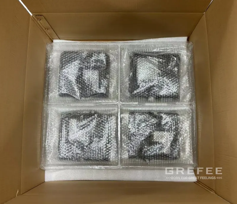
Packaging
At the At the beginning of the project, our engineers will design packaging schemes for the characteristics of the product. For this project, we utilized a single product wrapped in foam and then put it into a vacuum forming box. The outer layer is sealed in a 7-layer kraft paper box, which can avoid damage during transportation so that it can be delivered to customer hands safely.
Customers were surprised by Grefee’s working efficiency. Let’s have a their feedback about the quality of our product.
We have gained more time on research and development with Grefee, . They sent us the samples to us at a price lower than other suppliers and with higher quality. Their engineering team is also very efficient. The responses are quick and professional. In addition, their QC team is also detailed and efficient. Although we are thousands of miles apart, the feeling they give me is as same as a friend communicating face-to-face.