LPIM over molding DFM report

Posted on : Oct 21 , 2022 By GREFEE
Directory
1. The requirement of product
2. The analysis of the product feasibility and suggestion
2.1. demould direction for over molding
2.2. The question of A part
I. Locating hole
II. Thickness
III.Tolerance of PCB.
2.3. The question of B part
I. GAP
II. Thickness
III.Sharp edge to round
IV.Tolerance of PCB
V. undercut
2.4. The question of C part
I. Plastic
II. Thickness
III.Sharp edge to round
3. Mould solution project
3.1. Mould and process project 1st:
3.2. Mould and process project 2rd:
1. The requirement of product:
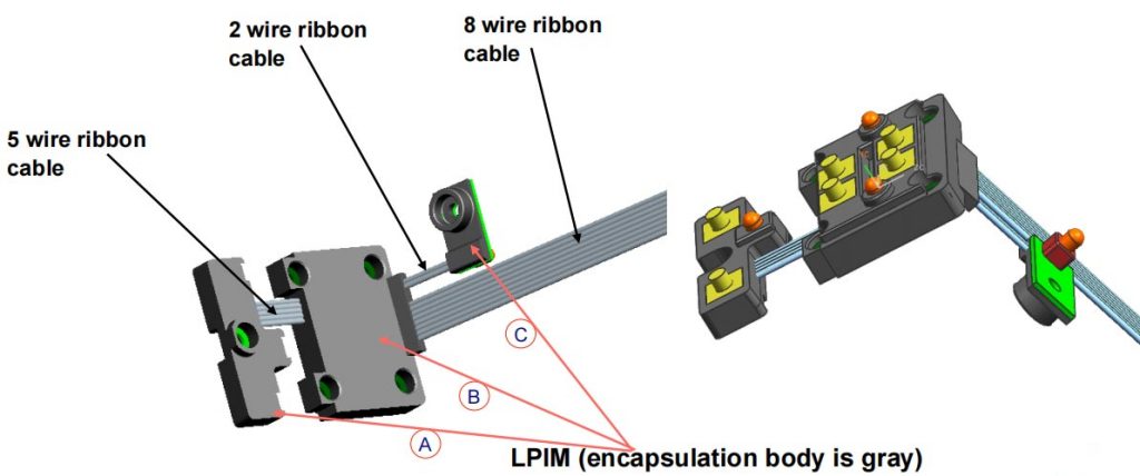
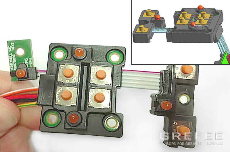
A. 31x 13.1x 7.7mm3 0.92 gram
B. 31x 25.6x 11 mm3 3.13 gram
C. 15.5x 8.2x 4 mm3 0.25 gram
2. The analysis of the product feasibility and suggestion
2.1 demould direction for over molding
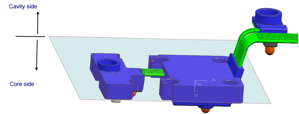
1. LED light is on core side because it must be located easily and stationery during opening the mould, so that avoid not to be scratched by mould
2.There is no draft-angle on the whole side of 3 parts (A,B,C), suggest to add 3°on it to prevent the sticky and scratch!
2.2 The question of A part
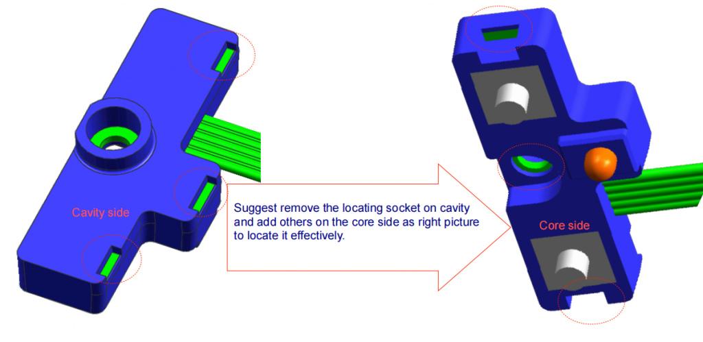
I. locating hole or socket for PCB in over molding is invalid because it is on the cavity side
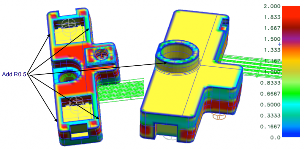
II. The analysis display that thickness of this part is even now. in order to good filling, suggest to add round R0.5 to avoid the short-shut
III. The 2 same units should be in a plane with high planeness(less±0.05), and the LED should be high tolerance in the position for the mould(less±0.05 too),otherwise it’s difficult to place the PCB to right site and would have risk to occur the serious flash

many flash, the tolerance of wires and other causes will affect the flash
2.3 The question of B part
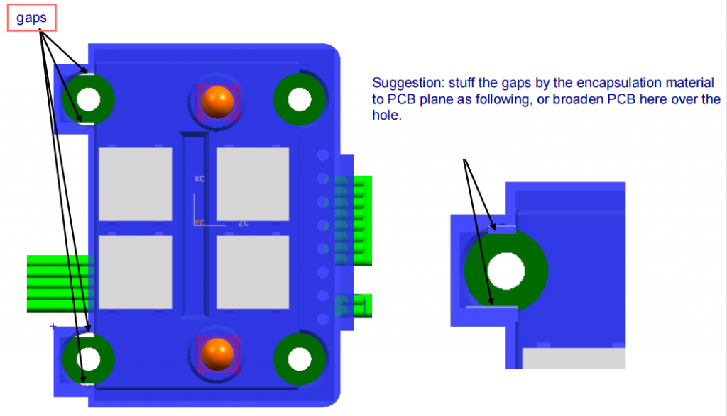
I. There are 4 places that have gaps as following, it’s sharp steel and very nondurable and easy to occur the flash in the mould.
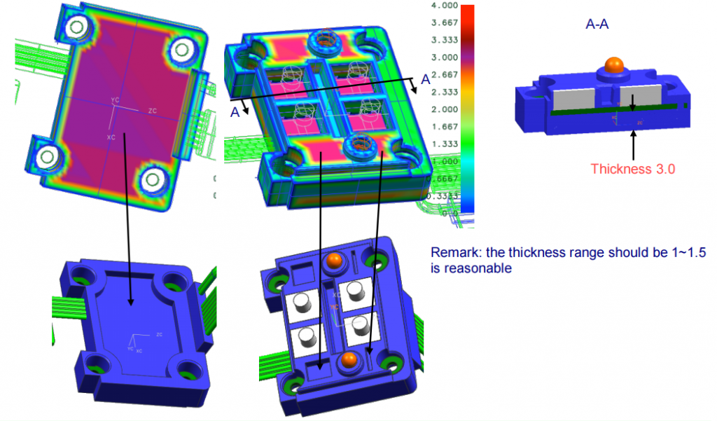
II. The analysis display that thickness of this part is very uneven. suggest make the recess on both side of part to avoid serious sink mark as following.
III. These places have sharp edge and corner to markedly reduce filling of moldflow, suggest add the round radius to improve moldflow and avoid short-shut.

IV. The 4 same units should be in a plane with high planeness (less±0.05),, and the 2 LED should be high tolerance in the position for the mould(less±0.05 too) ,otherwise it’s difficult to place the PCB to right site and would have risk to occur the serious flash
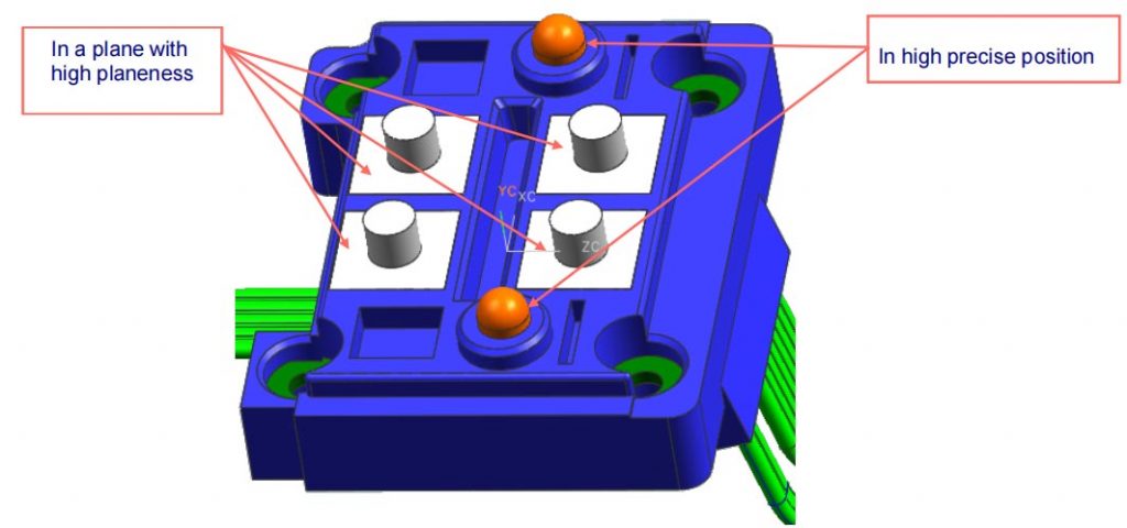
many flash, the tolerance of wires and other causes will affect the flash
V. There are a undercut between the slope wires and B part, it would make mould and process very complicated, and cause that mould have to take a lot of time to position the wire correctly. The mould and process is on following page 16
Suggest change the slope convex a little to as following, so when make the mould and molding, the wire could be flattened, the mould and process will become easy. The mould and process is on following page 17

2.4 The question of C part
I. Are the zone of part the encapsulation plastic?

II. The analysis display that thickness of this part is bit uneven. suggest remove some material of part to avoid probably sink mark as following.

III. There are some sharp edge where it’s probable to short-shut, so suggest make some round radius to reduce the influence
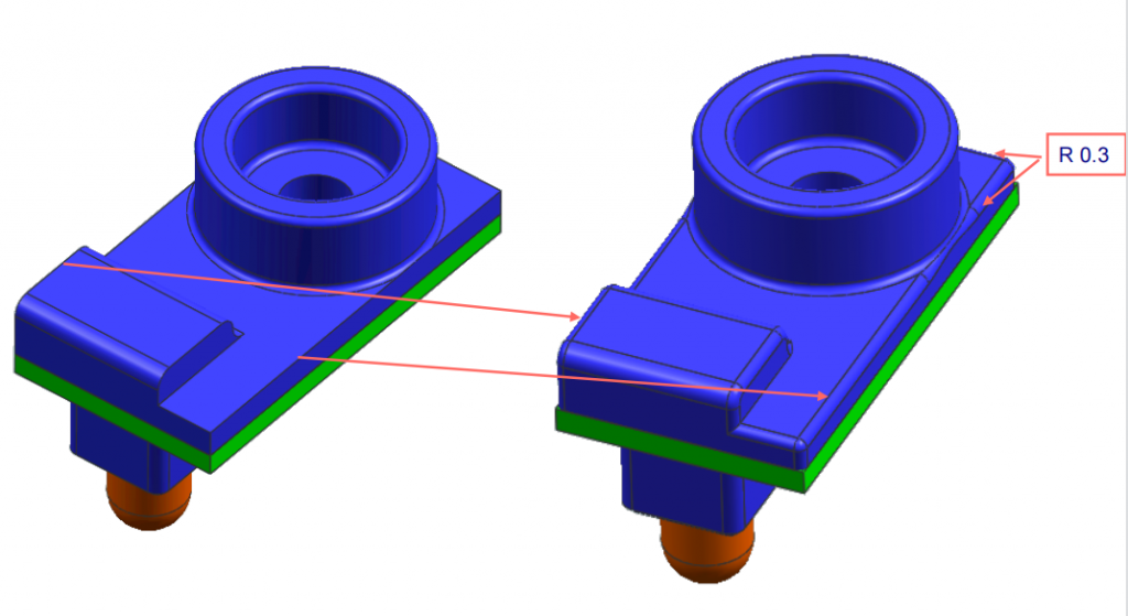
3.1 Mould and process project 1st: it’s for the original undercut structure of the assembly


3.2 Mould and process project 2rd: it’s for the no undercut structure of the improved assembly


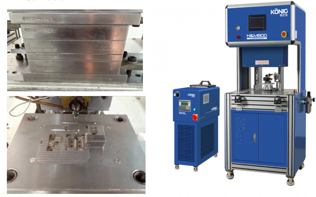
Mold and equipment
Final actual product

MORE BOLG
Insert mold in injection mold service
What are advantages and disadvantages of Zinc alloy and Aluminum alloy?
Inspection standards for injection molded partappearance
How to judge the quality of your plastic products?
Inspection standards for CNC machining
To ensure that your products are 100% qualified
Categories

Try GREFEE now,for free
We keep your uploaded files confidential and secure.

