Common issues of TPU Injection Molding

Posted on : May27, 2022 By GREFEE
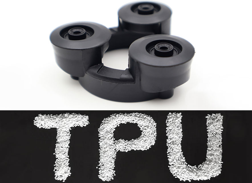
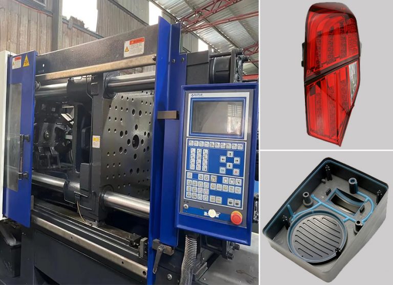
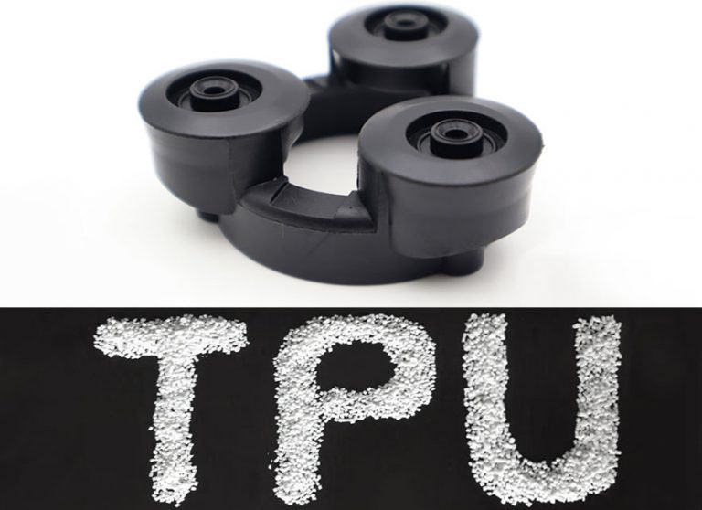
TPU injection molding processing includes injection molding, blow molding, compression molding, extrusion molding, etc. Among all the methods, injection molding is the most common one. Injection molding is used to make TPU into the needed parts and split the process into three stages pre-molding, injection, and extrusion. The injection machines are classified into two types, plunger type, and screw type. The screw-type injection molding machine is better because of its equal speed, plasticizing, and melting.
Design of TPU injection machines
(1). The barrel of the injection machine is coated with copper-aluminum alloy, and the screw bar is plated with chromium to prevent wear. Screw length diameter ratio L / D=16~20 is suitable, but at least 15. The compression ratio is 2.5/1~3.0/1. The length of the feeding section is 0.5L. The compression section is 0.3L, and the metering section is 0.2L. The check ring should be placed near the top of the screw to prevent backflow and maintain maximum pressure.
(2). It is suitable to use the artesian nozzle to manufacture TPU. The exit is in an inverted cone shape. The nozzle diameter is above 4mm, which is less than the inlet loop (0.68mm). There should be a controllable heating belt on nozzles to prevent material from being solidified.
(3). Considering the economic aspect, the injection amount should be 40%-80% of the rated quantity. The screw rotating speed is 20-50r/min.
Design of TPU injection mold
GREFEE is a tpu injection molding in china.You can contact us.
Considerations in mold design:
(1). shrinkage rate of molded TPU parts
- Many factors affect the shrinkage rate, such as stiffness of raw material, thickness, shapes, molding temperature, mold temperature, and other molded conditions. Typically, the shrinkage rate range is 0.005~0.5px/cm. For example, in a 100×10×2mm rectangular test piece, the gate at the 100m side shrinks in this flow direction, and the hardness of 75A is 2-3 times greater than that of 60D. When the TPU stiffness is from 78A to 90A, the shrinkage rate decreases as the increase of thickness but increases as the thickness goes up when this value is from 95A to 74D.
(2). runners and cold-slug well
- The main runner is a pathway that connects the injection machines nozzles to the shunts or cavities. The diameter should be expanded inward at 2 degrees upward to void the slugs out of the mold. The shunts are the parts that connect the main runners to each cavity. The display on the mold should be symmetrical and in equidistant distribution. The runners could be in different shapes, either in a circle, semi-circle, or rectangular. The suitable diameter value range is 6~9mm. The runner surface must be polished as the cavity to reduce the flow resistance and provide a quicker mold filling speed.
- The cold-slug well is an empty cavity set at the end of the main runner to collect the cold slugs that are generated between two injections at the nozzle ends to prevent the shunts or gates from being blocked. When the cold slugs enter the cavity, it is easy for parts to generate internal stress. The diameter of the cold slug well is 8~10mm, and the depth is about 6mm.
(3). gate and exhaust port
- The gate is the part that connects the main runners and shunts to the cavities. Its cross-section area is smaller than the runners, which is the smallest part of the runner system. The length of the gate should be short. There are rectangle or circle shape gates, of which the size increases as the thickness increase. When the thickness is less than 4mm, the diameter is 1mm. When the thickness is 4~8mm, the diameter is 1.4mm. When the thickness is over 8mm, the diameter is 2.0~2.7mm. The gate should be installed a the thickest area without affecting the use and appearance and forms a right angle with the mold wall to incase the porosity and spirals.
- The exhaust port is the grooved air outlet inside the mold to prevent the melts from being trapped in the gas. Gas is voided through the exhaust port to avid the air holes, poor welding, and insufficient mold filling. What’s more, it also helps with the prevention of burn and internal stress generation resulting from the high temperature caused by compressed air. An exhaust port could be installed at the end of the melt in the cavity or the parting surface of the mold, which is a 0.15mm deep and 6mm wide groove. It should be noticed that an even mold temperature is necessary in case the warpage and distortion.
Molding conditions of TPU injection molding
The most important molding conditions of TPU are cooling temperate, pressure, time, and plasticizing flow. These parameters affect the appearance and properties of the TPU parts. Good machining conditions help produce parts with uniform white or beige color.
(1)temperature
Parts that need temperature control in the molding TPU process include barrel temperature, nozzle temperature, and mold temperature. The former two affect the plasticization and flow, and the latter affects the flow and cooling of TPU.
A. Barrel temperature: the barrel temperature selection is related to the stiffness of TPU. The melting temperate of TPU is high when the stiffness is high. The highest temperature of the barrel end will increase, too. The barrel temperature range for processing TPU is 177~232℃. The barrel temperature distribution is typically from one side of the barrel to the nozzles (front end), then goes up gradually to render the TPU temperature rise smoothly to achieve uniform plasticization.
B. Nozzle temperature: the nozzle temperature is often a bit lower than the highest temperature of the barrel to prevent the casting of melts at the straight-through nozzles. Provided that using the elf-lock nozzles to eliminate the casting, the nozzle temperature can be controlled within the highest temperature range of the barrel.
C. Mold temperature: mold temperature has a big influence on the internal properties and surface quality of the TPU parts. Its level determines many factors like crystallinity of TPU and size of parts. Mold temperature is often controlled through the constant temperature cooling mediums, like water. The high the TPU stiffness, the higher the crystallinity, and the higher the mold temperature, like the Texan, hardness 480A, mold temperature is 20~30 degrees; hardness 591A, mold temperature 30~50 degrees; hardness 355D, mold temperature 40~65 degrees. The mold temperature of the TPU parts is typically within 10~50 degrees. Low mold temperate will lead to the castings due to the premature frozen melt, which is no benefit for the increase of the crystal. Meanwhile, the crystallinity of parts decreases, leading to the shrinkage and property alteration of parts in the late stage
(2). pressure
A.The injection molding process includes the plasticizing pressure (back pressure) and injection pressure. When the screw bar moves back, the pressure that the melt on the top bears is the back pressure, adjusted by the overflow valve. The increase in back pressure will raise the melt temperature and reduce the plasticizing velocity. This situation renders an even melt temperature and the pigment mixing. It also exhausts the gas in the melt in the meantime but will extend the molding cycle. The back pressure of TPU is usually within 0.3~4MPa.
B.The injection pressure is the pressure exerted by the top of the scree bar on the TPU, which functioned to overcome the flow resistance of TPU from the barrel to the cavity, fill the mold with molten material, and compact the molten material. The flow resistance of TPU and the mold filling efficiency are related to the melt viscosity closely, whereas the melt viscosity is related to the hardness of TPU and melts temperature, which refers that the viscosity of melts is not only determined by the temperature and pressure but also determined by the hardness and deformation rates of TPU. The higher the cutting speed, the lower the viscosity. The higher the TPU hardness, the higher the viscosity. While, the cutting speed remains leveled up.
C.With an unchanged cutting speed, the viscosity decreases as the increase of temperature. However, the temperature has a higher impact on the cutting speed than viscosity. The injection pressure of TPU is typically within 20~110MPa. The holding pressure is almost half of the injection pressure. The back pressure is below 1.4 MPa, making the plasticization of TPU uniform.
(3). Time
The time needed for completing an injection molding process is called the molding cycle. The molding cycle includes mold filling time, pressure holding time, cooling time, and other times (mold opening, mold releasing, mold closing, etc) that affect production efficiency and equipment utilization rates directly. The molding cycle of TPU is determined by its hardness, thickness, and structure of parts. The high hardness of TPU leads to a short molding cycle. The thicker mold thickness results in a long cycle. The more complex the structure of the mold, the longer the molding cycle. Other factors affect the molding cycle, like temperature. The molding cycle of TPU is within the 20~60s.
(4). injection speed
The injection speed is determined by the structure of the TPU part. Those with thick end face only needs lower injection speed. The thin-end face will cause a quick injection speed.
(5). rotating speed of screw bar
Processing TPU parts needs low cutting rates, so the slower, the better. The rotating speed of the screw bar is typically from 20~80r/min or 20~40r/min for the optimal choice.
(6). shutdown processing
Since TPU is likely to degrade under a high temperature. Hence, clean the machine with PS, PE, acrylate plastic, or ABS after shutdown. If the shutdown period is over 1 hour, shut down the machine and heat.
Post treatment of parts
Due to the uneven plasticization in the barrels or various cooling rates in the cavities, there is often non-uniform crystallization, orientation, and shrinkage. Thus, the internal stress is generated in the part, especially more obvious in the thick wall parts or parts with metal inserts. Parts with internal stress often appear chemical performance decreased issue in the storage and use. There are the craze, deformation, and even cracks on the surface.
In production, a common way to deal with these issues is to carry out an annealing process for parts. The temperature of annealing varies with the hardness of the TPU parts. The hardness decreases as the temperature decreases. A too high temperature might cause warpage or deformation. A too low temperature might fail to achieve the purpose of removing the internal stress. The annealing of TPU should use a low temperature for a long time. Parts with low hardness are placed under room temperature for weeks can achieve the optimal property. Hardness under Shore A85, annealing: 80℃×20h. Hardness over A85, annealing: 100℃×20h. The annealing can be processed in a hot air oven. The place position shouldn’t be too hot in case of the deformation of parts.
Annealing not only removes the internal stress but also enhances the force performance. Since the TPU is two-phase morphology, phase mixing occurs during TPU hot processing. Due to the high viscosity, the phase separation is slow when cooling quickly. There must be sufficient time to separate it to form the micro area for the optimal property.
Inlay injection molding
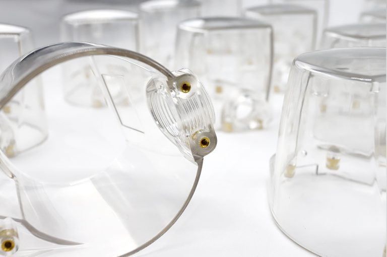
To meet the needs of assembly and strength, a metal insert will be inserted into the TPU part. This metal insert will be placed at the predetermined position to get a whole part through the injection. Due to the difference in thermal properties and shrinkage rates of TPU parts and metal parts, the insert is not stuck firmly with TPU. The solving solution is to pre-heat the metal insert. After pre-heating, the insert reduces the temperature difference of melts, so the melts around the inserts are cooled slowly in the injection process but shrunk evenly. It provides a feeding effect to stop too much internal stress generated around the inserts. The TPU inlay molding is easy, and the insert shapes are not limited. After the inserts fall off, we can heat the inserts at 200 ~ 230 degrees for 1.5~2 mins, and peeling strength can reach 6~9kg/25mm to ensure a firm adhesion. Applies the adhesives on the inserts, heat them at 120degrees, then process the injection. Besides, all the TPU used cannot contain lubricates.
Reuse of the recycled material
In the processing of TPU, the main runner, shunts, unqualified parts, and other scraps can be reused. From the laboratory report, 100% recycled material does not mix with any new material. The decrease of the force properties is not evident and can be utilized. However, to maintain the physical force properties and injection conditions at the optimal level, it recommends that the ratio of the recycled material should be within 25%~30%. Moreover, the specification and type of the recycled and new material should be the same. Recycled material that has been polluted or annealed is forbidden to use and does not keep it stored for too long. It is better to dry it immediately for use. The melt viscosity of recycled material will decrease and adjust the forming conditions.
Common injection defects
(1). Parts depression:
PU part surface defects will lower the quality, strength, and appearance of products. The cause of depression is associated with the used material, molding technology, and mold design. More specifically, factors include shrinkage rates, injection pressure, mold design, cooling devices, etc.
(2).bubbles:
in the injection molding process, many parts have bubbles, which will affect their strength and mechanical performance, and also impacts the part’s appearance negatively due to uneven thickness or protruding ribs. The cooling speeds of different materials are different in molds, which leads to non-uniform contraction and bubbles. Therefore, we should pay attention to the mold design.
Moreover, if the raw material is not dried completely, the melts will degrade into gas when being heated and are easy form bubbles in the mold cavity. When parts have bubbles, check the factors below and carry out the process in time.
(3).cracks on parts:
Cracks are lethal for TPU parts. Common signs are hair-shaped cracks appearing on the parts’ surface. When a part has sharp corners, it is not easy to see the thin cracks in this area. This is dangerous, and the primary reasons for cracks are below:
- Difficult to release the mold
- Overfilling
- Mold temperature is too low
- Defects on part structures
To avoid cracks, due to the poor mold releasing, the molding area should have sufficient mold releasing obliquity. The size, position, and mode of the ejector pins should be appropriate. When ejecting, the mold release resistance of each part of the finished product should be uniform.
Overfilling. Overfilling is caused by too much injection pressure or the amount of material, which increases the internal stress and causes cracks when releasing the mold. Under this condition, the deformation of the mold accessories increases, too. This renders the mold releasing more difficult and deteriorate the cracking. The method to deal with this is to reduce the injection pressure and avoid overfilling.
Around the gate, there is often residual internal stress. The surrounding gate tends to be brittle, especially the part of the direct gate, which is easy to crack due to the internal stress.
(4 ).warpage and deformation
TPU injection parts have warpage and deformation due to the short cooling period, high mold temperature, and uneven and asymmetrical runner system. Thus, avoid the below points when designing the mold.
- The thickness difference of the same plastic part is too large;
- Excessive acute angle;
- The buffer zone is too short, which makes the thickness of turns vary greatly;
Besides, it needs to set appropriate number of ejector pins and mold cavity cold runners.
(5).Parts with focal spots or black lines
Focal spots or black lines refer to the phenomenon in which black spots or stripes on the parts, resulting from the poor thermal stability and decomposition of raw material.
One solution to effectively manage the focal spots or black lines is to prevent the temperature in the barrel from being too high and slow the injection speed. If there are scars or notch on the inner wall of the melts barrel or screw, raw material is likely to adhere to the wall. These raw materials will be degraded due to over hot. Besides, the check valve will also cause thermal decomposition due to the retention of raw materials. Thus, when using raw material with high viscosity and degradable raw material, we should prevent the generation of focal spots and black lines.
(6).parts have burrs
Burr is a common phenomenon in manufacturing TPU parts. When the pressure in the cavity is too high, the parting force outweighs the clamping force so that the mold is forced to open, and raw material overflow to form burrs. Many factors could cause burrs, such as raw material, injection molding, inappropriate modification, or mold. Hence, when looking for the generation of burrs, it is better to start from easy to hard.
- Check whether the raw materials are thoroughly baked, mixed with sundries, mixed with different kinds of raw materials, and the influence of raw material viscosity;
- Correctly adjust the pressure-controlled system of injection molding machines, and the adjustment of the injection speed should match the clamping force.
- Whether the mold are worn, exhaust holes are blocked, runner design is reasonable or not.
- Whether there is a deviation in the parallelism between injection molding machine plates, whether the force distribution of template pull rod is uniform, and whether the screw check ring and melt barrel are worn.
(7).parts sticking of mold (difficult mold releasing)
When TPU sticks to the mold during injection molding, the first is to consider whether the injection pressure or holding pressure is too high. High injection pressure results in over-saturation of parts, filling other gaps with raw materials, and making parts stuck in the mold cavity, resulting in mold releasing difficulty. Apart from that, when the temperature of the barrel is too high, the raw material will decompose or deteriorate the raw material when heated, causing mold to stick due to cracks or fractures in mold release. In terms of the mold, such as inlet imbalance, making the cooling rates inconsistent, or leads to mold sticking.
(8).Reduced toughness of parts
The toughness is the energy that leads to material cracking. Factors that lead to toughness decrease are raw material, recycled material, temperature, mold, etc. The decrease of the toughness will directly affect the strength and mechanical performance.
(9).insufficient filling of TPU parts refers to the phenomenon that the molten material does not thoroughly flow through all corners of the forming chamber.
The insufficient filling is caused by the inappropriate molding settings, the design, and manufacture of the mold are problematic, the material thickness of the finished product or the wall is thin, etc. Molding methods are increasing the material, mold temperature, injection pressure and speed, and flowability of material. In the aspect of molds, we can enlarge the runner or runner sizes or the size and numbers of the gate to process the modification to make the melts flow smoothly. Moreover, to exhaust the air in the room, we can set the exhaust ports in proper positions.
(10). The bonding line is the thin line formed by the confluence of two or more molten materials, also called the welding lines. The bonding lines not only affect the appearance and strength of parts. Causes for bonding lines:
- Flow mode of material caused by the shapes of parts (mold structure)
- Poor confluence of molten material.
- The air, volatiles, or refractory materials are mixed at the confluence of molten materials.
Increasing the material and mold temperature will minimize the bonding lines. Meanwhile, changing the position and number of the gate will move the bonding lines to other places, set venting holes at the melting site to quickly disperse the air and volatiles, or the overflow groove around the bonding site and move the bonding line to the overflow groove, then cut it off.
(11). TPU parts lost the gloss of material and form film or fuzzy state, which is called poor gloss surface.
Poor gloss surfaces are largely caused by the poor grinding of the mold surface. When the surface of forming space is in good condition, increasing the temperature of material and mold can enhance the surface gloss of parts. Excessive use of refractory agents or greasy refractory gents is also the cause of poor surface gloss. Meanwhile, moisture absorption of materials or contamination by mixing volatiles and impurities are also the cause of poor surface gloss of parts. Therefore, we should pay attention to the issues of mold and material.
(12). Parts have flow marks (line pattern)
The flow marks are traces of molten material flow. Stripe pattern centered on gate.
The flow marks into the forming space cool too fast, resulting in a boundary between the material flowing in after it. To prevent the flow marks, we can increase the material temperature and flowability and adjusts the injection speed.
The cold material left in the front end of nozzles will cause flow marks when it enters the space directly. Thus, set a sufficient stagnant part at the junction of sprue and runner or the conjunction of runner and shunt, which can prevent the flow marks effectively. Meanwhile, increasing the gate size is also helpful.
MORE BOLG
Categories
Latest blog

Try GREFEE now,for free
We keep your uploaded files confidential and secure.

