Design tips for die casted parts

Posted on : March 9, 2022 By GREFEE
Concept
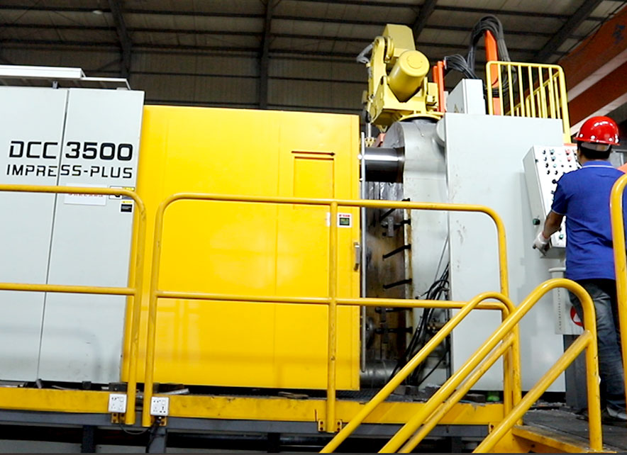
Die casting is a technology of manufacturing metal parts that liquid metal or semi-liquid metal fill the die casting cavity at a high speed under high pressure to get a metal part after solidification under pressure.
The outstanding features of die casting technology are high pressure, high speed and high temperature.
Advantages
High production efficiency, it’s easy to achieve mechanization and automation in the production process.
Die casted parts have high dimensional precision and high surface quality.
Die casted parts have better mechanical performance`.
Can die cast complicated thin-walled parts.
Die casted parts can be inserted with components from other materials.
Disadvantages
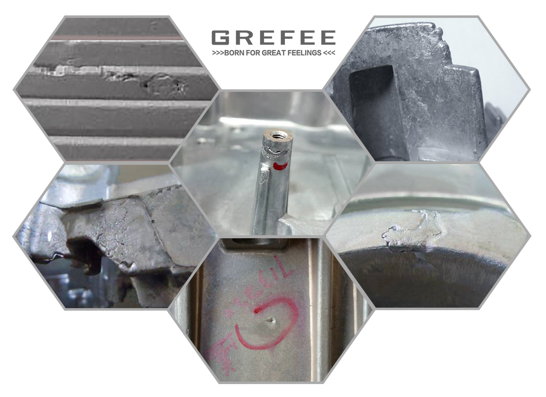
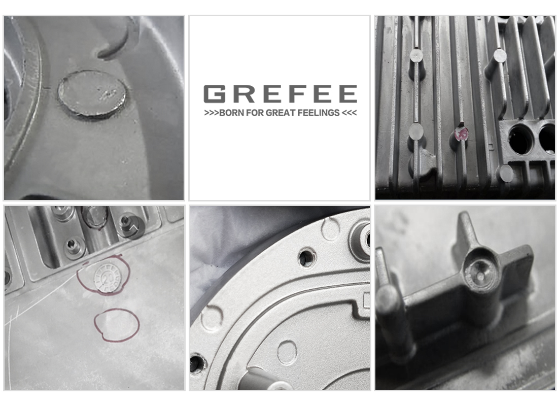
holes occur easily in die casted parts
not suitable for small batch production
Mold life is relatively short for die casting alloys with high melting points.
Advantages of die casting
Compared to plastic parts: high strength, has properties of electrical conductivity, thermal conductivity and electromagnetic radiation resistance
Compared to sheet-metal parts: part structure can be more complicated, wall thickness can be changed, a die casted part can replaces several sheet metal parts, simplify the product structure.
Compared to CNC machined parts: die casted parts have lighter weight and lower cost.
Compared to other casting methods: die casted parts have higher dimensional accuracy, better surface quality and higher production efficiency.
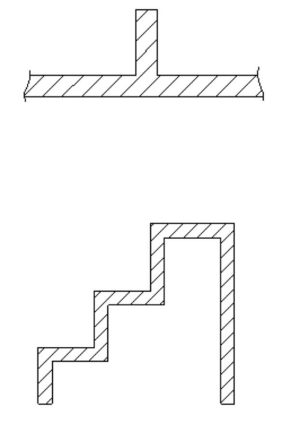
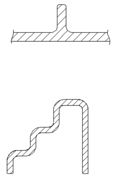
Wall thickness of the die casted part
Proper wall thickness of the part
Too thin wall thickness: it’s hard to fill and it’s easy to cause insufficient filling.
Too thick wall thickness:
Cause defects such as coarse internal grains, shrinkage cavity, holes, outer surface problem and mechanical properties declining.
Increase part weight and manufacturing cost.

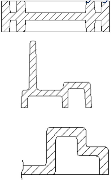
Even wall thickness of the part, and even transition around thickness changing areas

Hole design for die casted parts
With too small hole, the cavity is easy to distort and break under impact then shorten the mold working life.

Avoid too thin thickness partly of die casting mold
With partly too thin thickness, the mold has low strength and the cavity is easy to distort and break under impact then shorten the mold working life.

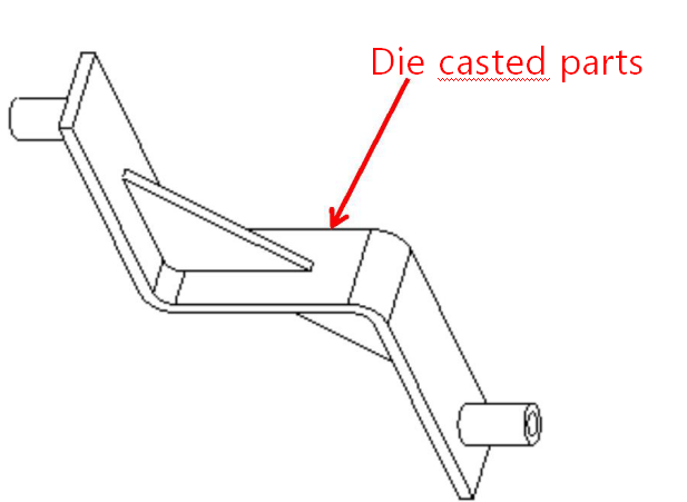
Design of reinforcing ribs
Sizes for reinforcing ribs
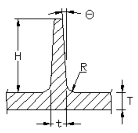
The root thickness of the reinforcing ribs generally not exceeds its wall thickness
The demolding draft of reinforcing ribs is 1°~3°.
Should add round corners at the root of the reinforcing rib to avoid sharp changes on part section, assist the molten metal to flow, decrease the stress concentration and improve the part strength.
Usually the round corner closes to the part thickness there.
The height of reinforcing rib not exceeds 5 times of its thickness
Improve part strength by adding reinforcing ribs, avoiding flat-plate design
Flat-plate parts have low strength, and are easy to distort.
Proper design of reinforcing ribs can improve the part strength and decrease the distortion of the parts.


Adding reinforcing ribs to assist the flowing of molten metal
assist molten metal to flow, improve the filling performance of the part
the direction of reinforcing ribs is consistent with the flow direction of molten metal.
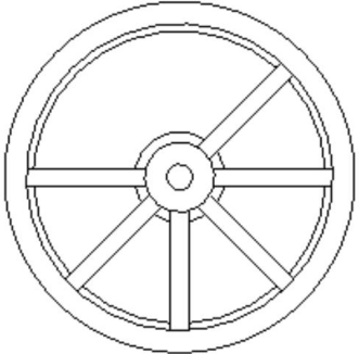
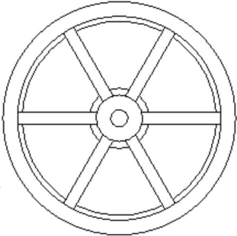
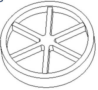
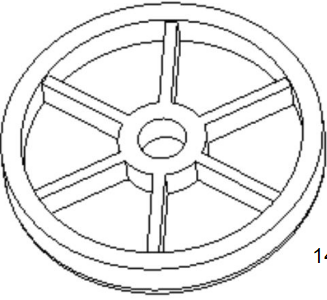
the position distribution of reinforcing ribs should be reasonable, and try to achieve symmetrical and even distribution as much as possible.
Avoid too thick wall thickness partly around connecting areas of ribs
Demolding draft
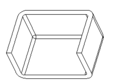
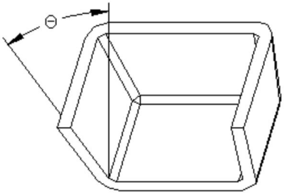
Since the different adhesion strengths between the three commonly used die casting alloys(aluminum alloy, zinc alloy, magnesium alloy) and their die casting molds, these three materials require different demolding drafts in die casting:
There’s large adhesion strength between aluminum alloy and its die casting mold, so the demolding draft of inner surface is generally 1°.
The adhesion strength between magnesium alloy and its die casting mold is slightly smaller than that of aluminum alloy, so the demolding draft of inner surface is generally 0.75°.
Zinc alloy has the smallest adhesion strength with its die casting mold, so the demolding draft of inner surface is generally 0.5°.
Design of round corners
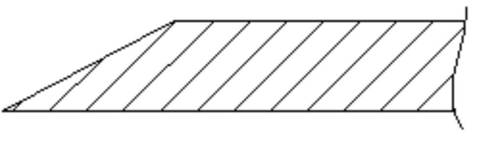
Avoid outer sharp corners
Too thin outer sharp corners are easy to cause problems such as insufficient filling, non-impact metal structure and low strength
Outer sharp corners are easy to cause security problems
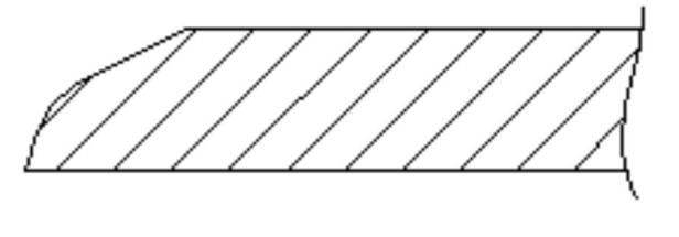
Design of inner round corners
Round corners have a great effect on the aspects of part quality, part performance and mold life.
assist the molten metal to flow, improve the filling performance, and facilitate the air venting
avoid stress concentration and improve the strength of die casted parts
improve the mold working life of the die casting mold
When the die casted part requires electroplating, round corners can achieve even coating to avoid deposition at sharp corners.
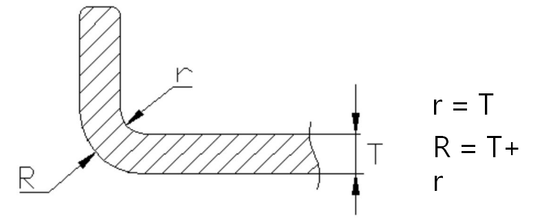
Design of inner round corners
Design of supporting pillars
Avoid too close distance between supporting pillars and part wall or between pillars
Too close distance is easy to cause thick wall thickness, so as to cause part defects such as depression, hole and shrinkage cavity.
cause mold problems such as too thin wall partly, low strength and short working life
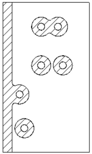
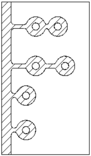
Add reinforcing ribs around the supporting pillars
Improve the strength of the supporting pillars
Assist the filling in supporting pillars
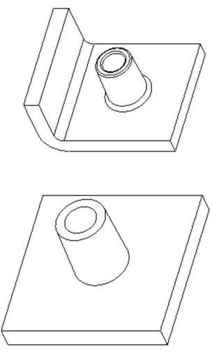
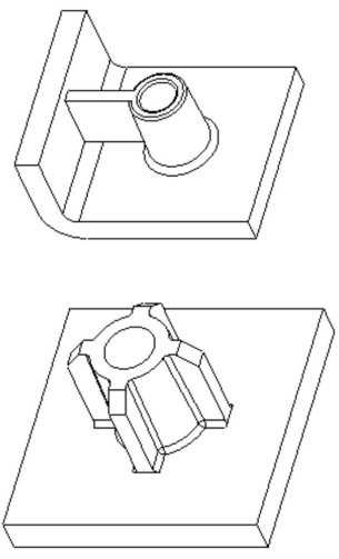
Re-design the inclined supporting pillars to simplify the mold structure
When the supporting pillars are inclined, proper design optimization can simplify the mold structure and save mold cost.
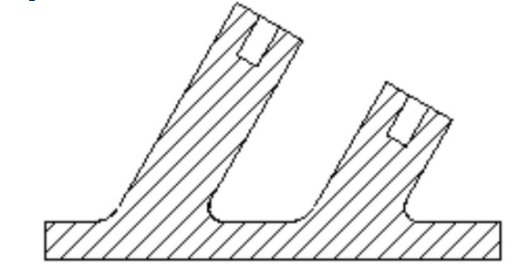
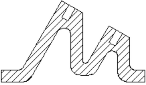
Lower the height of supporting pillars as much as possible
The height of supporting pillars cannot be too high, otherwise, the pillars have low strength and are hard to fill.
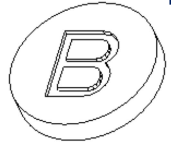
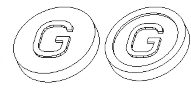
Design of letters
It’s better to design the letter that protrude from the part surface
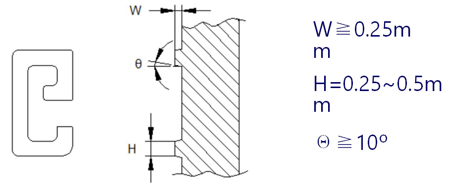
Sizes of letters
Design of threads
Avoid full thread designing for external threads
Full thread designing makes the parting lines hard to align
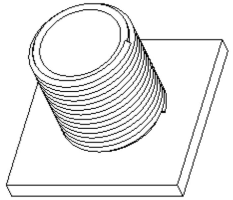
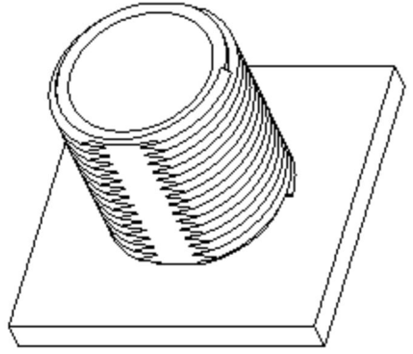
Avoid direct die casting of internal threads
Direct die casting requires special structure and high mold cost
Convenient design for removing burrs and gates
Avoid strict requirements on removing burrs and gates
reduce process, decrease cost
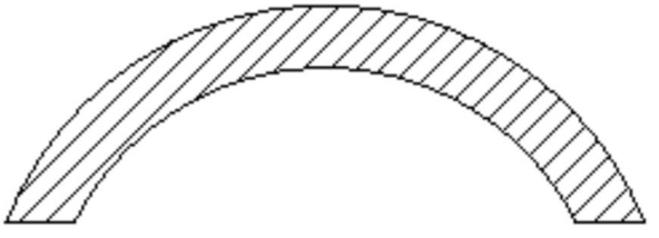
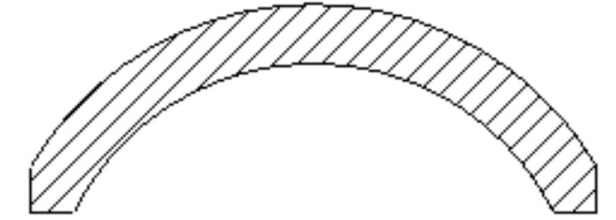
Avoid an acute angle between part wall and parting line
it’s hard to get rid of burrs and flash if there’s acute angle between part wall and parting line
burrs and gates are easy to remove by adding a section of plane about 1.5 mm.
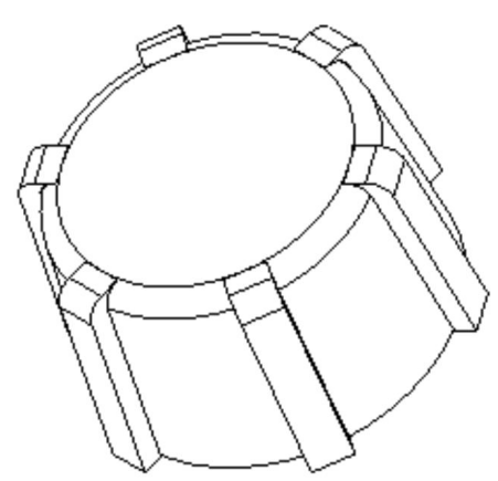
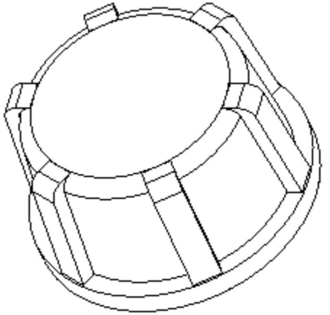
Simplify parts and avoid complex parting line shapes
Burrs around parting lines are hard to remove if parting lines are in complicated shapes, which increases the part cost
Burrs can be removed easily by simplifying part shapes and avoiding complex parting line shapes.
Tolerance of die casted parts
Try to minimize the tolerances of die casted parts
Under the premise of meeting the requirements on part working performance, try to adopt loose tolerances for die casted parts, as strict tolerances will increase the part cost.
Strict part tolerances must require strict mold tolerances, which must increase the mold cost.
The working life of die casting mold will shorten because of high tolerance requirements.
In order to maintain strict dimensional tolerances of parts, die casting molds must be maintained and replaced frequently.
Using more die casted parts and high frequency of dimensional inspection on die casting molds to ensure strict tolerance of parts, which will increase the part cost.
Higher defect rate on die casted parts
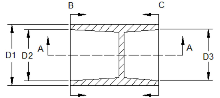
Properly choose the parting lines, and improve the precision of important dimensions of the part
If the concentricity of D1 and D2 is very important, choose C-C as the parting line
If the concentricity of D1 and D3 is very important, choose B-B as the parting line
To ensure the same diameters of D1 at the left end and right end, choose A-A as the parting line
Simplify the mold structure and low down the mold cost
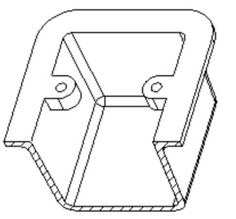
Avoid internal side concaves
Internal side concaves can be achieved by side core-pulling structure or by secondary machining, which will greatly increase the cost of molds or products
Proper part design can reduce the cost of molds or products by avoiding Internal side concaves.
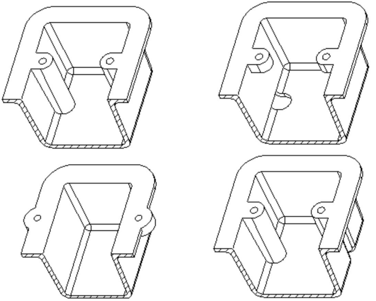
Avoid external side concaves
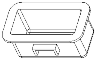
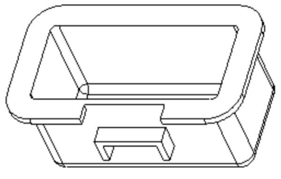
Avoid blocking the core-pulling structure
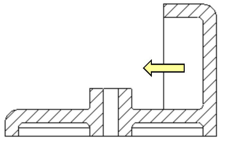
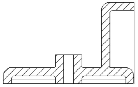
avoid round corners in parting surface
When there’re round corners in parting surface, the die casting mold has complicated structure and is hard to manufacture, besides, low strength around the round corners makes the mold working life decline.


Machining
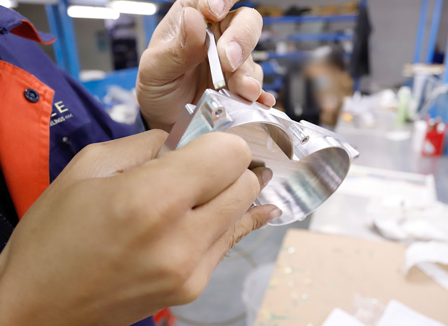
Avoid machining
Die casted parts should avoid machining as much as possible, and the reasons are:
Die casted parts can achieve high dimensional accuracy and surface quality. In product designing, can loosen the requirements on dimensions and surface quality to avoid machining on die casted parts.
Die casted parts has strong impact layer on surface and high mechanical property. Machining may damage the impact layer on die casted part surface.
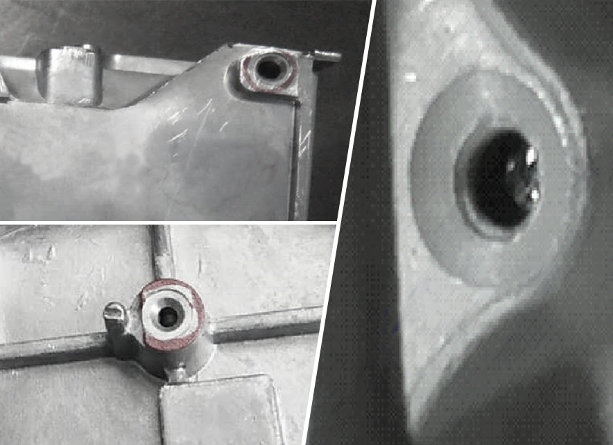
Sometimes die casted parts may have holes inside, which may be exposed after machining and then affect the part working.
Machining will greatly increase the part cost
Die casting parts are designed to facilitate machining and reduce the machining area
Should design the part to suit die casting for facilitating machining and reducing machining area, so as to decrease the machining cost.
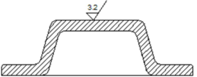
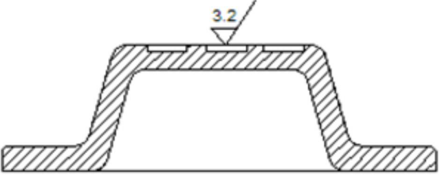
The less machining allowance, the better
The outer surface of the die casted part is a compact layer, while the interior is relatively loose, with pores and pinholes.
Therefore, it’s better to keep the less machining allowance for die casted parts to prevent damaging its compact layer.


Use die casted parts to simplify the product structure and low down the product cost
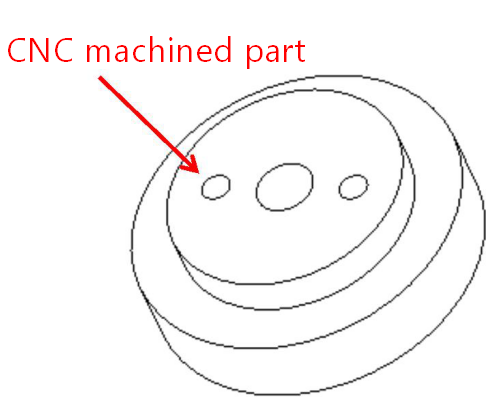
Die casted parts replace CNC machined parts
With the advantage that die casting cost is lower than CNC machining cost, use die casted parts to replace CNC machined components to greatly decrease the part cost under the premise of meeting part strength and dimensional accuracy.
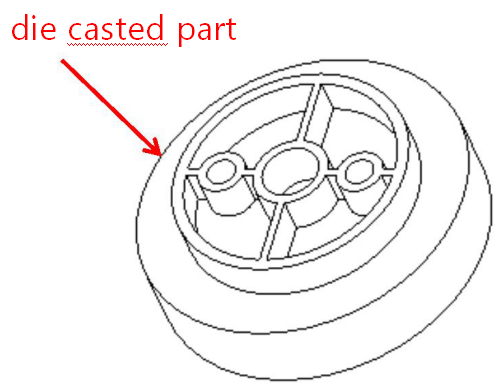
Die casted parts replace plastic parts
take advantage of the die casted part’s property of anti – electromagnetic radiation.
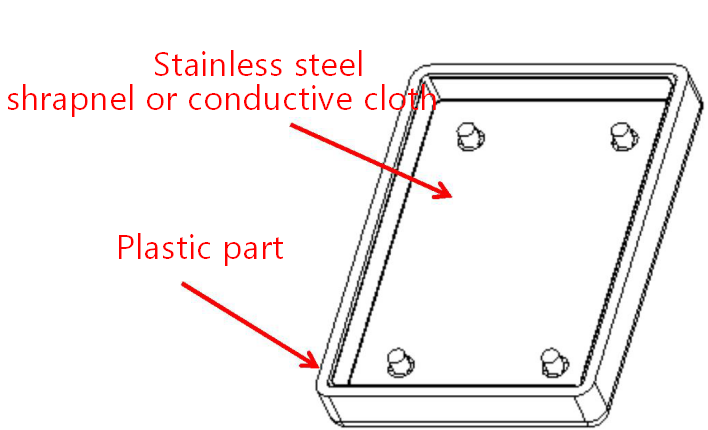
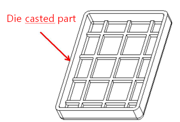
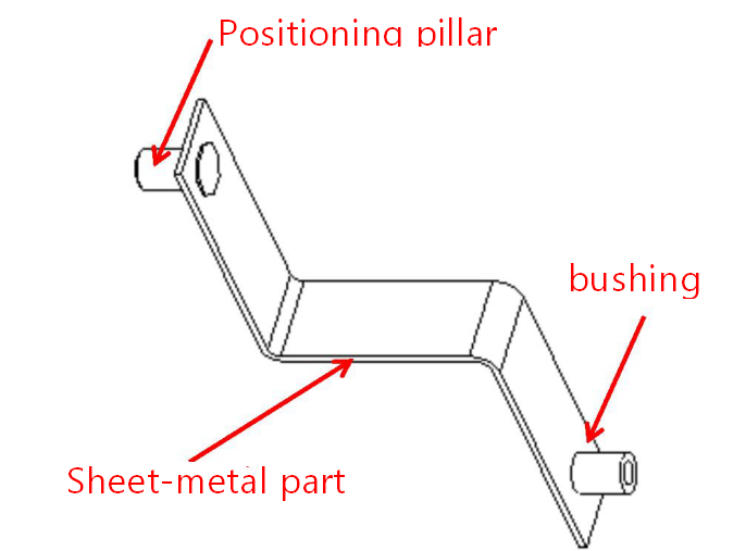
Die casted parts replace sheet-metal parts
Take advantage of the complex structure of die casted parts

Try GREFEE now,for free
We keep your uploaded files confidential and secure.
